I could not find a proper document and hence I thought I will write this article so that this might help the other engineers using ESXi to build the virtual topologies more effectively.
I am using Vios-L2 image for this demo. Please do not ask me for this image and I am not going to SHARE this.
I am currenlty labbing from the Narbik Workbook. Please visit http://www.micronicstraining.com/ for their Workbook material.
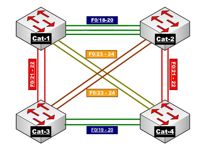
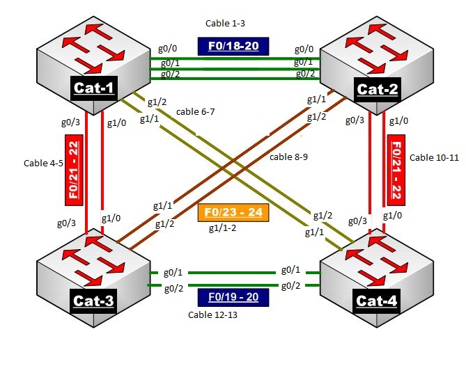
I am going to show you how you can make the above topology virtually. The CCIE R n S version 5 is Vitual and hence I thought of implementing the same.
Looking at the above diagram, we see that we would need 4 x Virtual-Switches and 13 cables to interconnect them.
Let’s get Started
First we will create cable connection so that we can connect between the switches.
In order to do that, select ESXi host and then go to Configuration tab and then click Add Networking as shown below.


Once you click Add Networking, follow the below procedure as shown below.
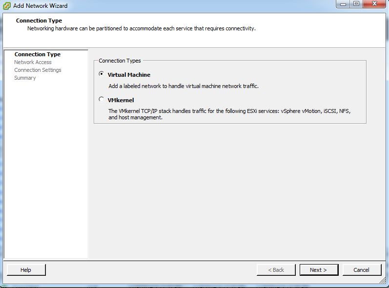
Select Virtual Machine and click NEXT
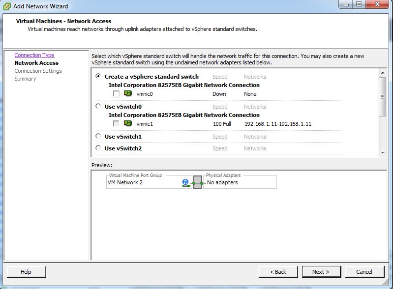
Make sure you un-select the VMNIC-0 as we just need a cable type connection so that we can connect two switches.
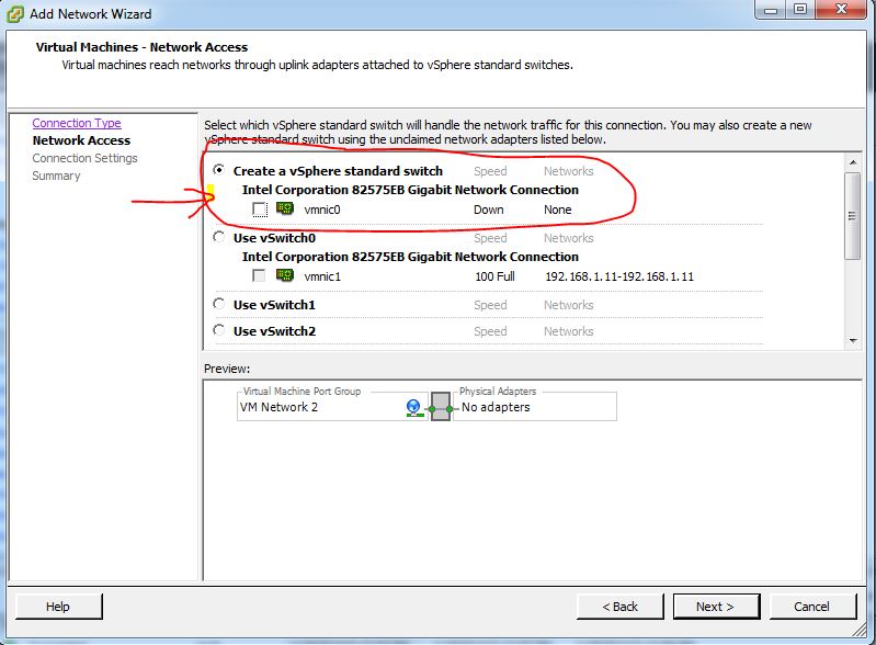
Once you un-select, hit Next.
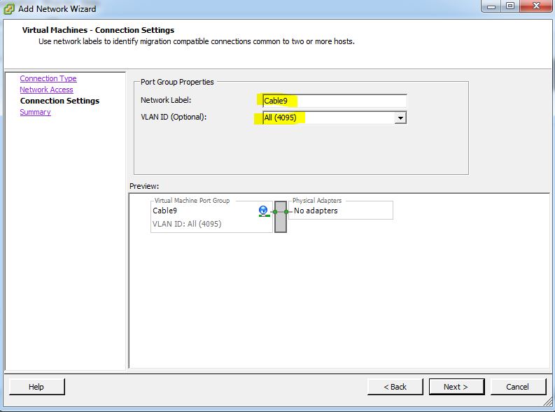
Give a meaning Full Name to the Network Label and Select Vlan-ID (4095) and hit Next.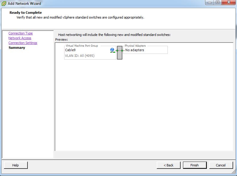
Now Click FINISH.
If you look under the configuration tab, you will see that the network connection is created and there is no adapters connected to it.
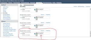
Using the above procedure, I have created 13 such connections.
I have connected 4 switches as per the below diagram.
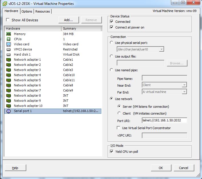
If we examine the Network adapter settings for Sw-1, you should set it like below.

SW-2 Network Adapter settings :
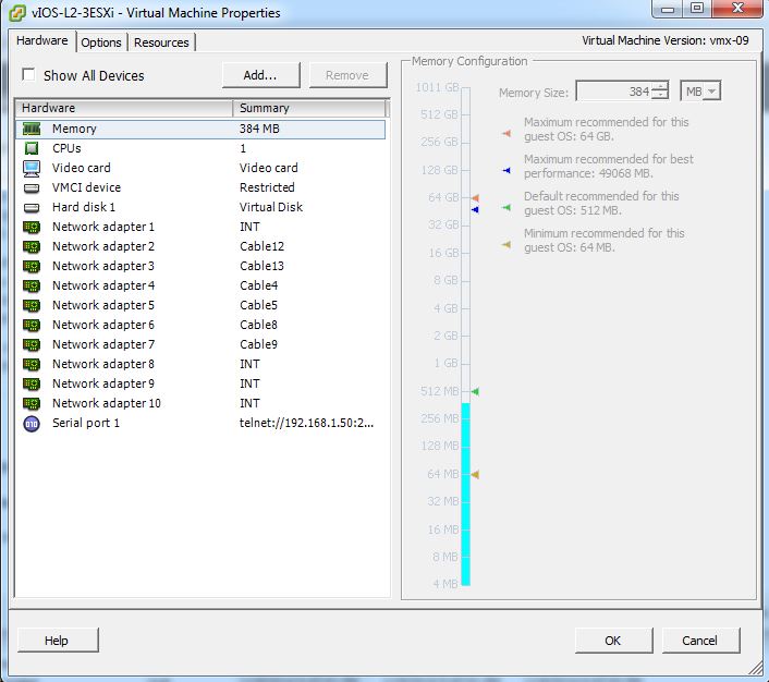
SW-3 Network Adapter settings :
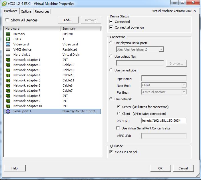
SW-4 Network Adapter settings :
Please note that the network adapters on these switches starts from G0/0 onwards.
Network Adapter 1 indicates its G0/0,
Network Adapter 2 indicates its G0/1,
Network Adapter 3 indicates its G0/2,
Network Adapter 4 indicates its G0/3,
Network Adapter 5 indicates its G1/0,
Network Adapter 6 indicates its G1/1,
Network Adapter 7 indicates its G1/2,
Network Adapter 8 indicates its G1/3,
Network Adapter 9 indicates its G2/0,
Network Adapter 10 indicates its G2/1.
As per my Understanding Cisco Vios images supports upto 10 Network Adapters. I might be wrong.
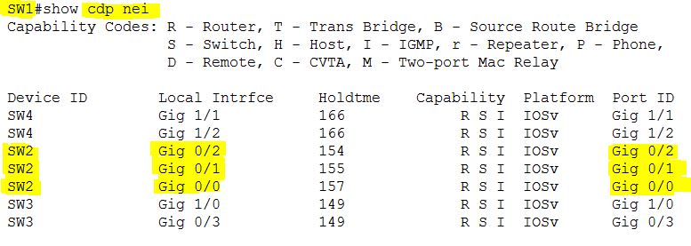
Let me start the switches and see what show CDP neighbor tells us 🙂
On SW-1 :
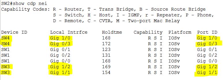
On SW-2
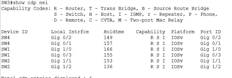
On SW-3
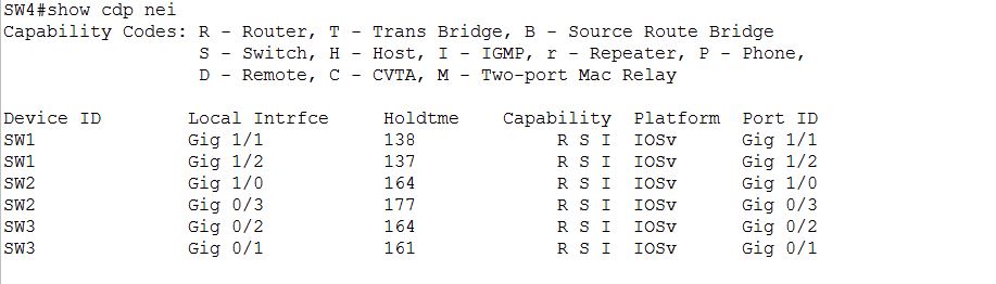
On SW-4
If you are using Vmware WorkStation then you can only make 19 connections and that is the maximum it supports.